Chapter 5 MX53 OBDS I2C Module
-- Mark Ding
5. iMX53 I2C setting.This chapter talking about OBDS I2C module in detail. We can customize the code base on customer’s hardware board.
5.1 I2C IOMUX setting.
In “src/mx53/hardware.c”, function void io_cfg_i2c(u32 module_base),
/* I2C1 mux'd out on CSI0_DAT8 and CSI0_DAT9 pads */
/* I2C1_SDA ALT5 on CSI0_DAT8 IOMUX setup */
writel(0x10 | ALT5, IOMUXC_SW_MUX_CTL_PAD_CSI0_DAT8);
/* I2C1_SDA is involved in the Daisy Chain */
writel(0x0, IOMUXC_I2C1_IPP_SDA_IN_SELECT_INPUT);
writel(0x1EC, IOMUXC_SW_PAD_CTL_PAD_CSI0_DAT8);
/* I2C1_SCL ALT5 on CSI0_DAT8 IOMUX setup */
writel(0x10 | ALT5, IOMUXC_SW_MUX_CTL_PAD_CSI0_DAT9);
/* I2C1_SCL is involved in the Daisy Chain */
writel(0x0, IOMUXC_I2C1_IPP_SCL_IN_SELECT_INPUT);
writel(0x1EC, IOMUXC_SW_PAD_CTL_PAD_CSI0_DAT9);
5.2 I2C module files.
5.3 I2C module funcions
- OBDS I2C transfer function is int i2c_xfer(u32 base, struct imx_i2c_request *rq, int dir). structure imx_i2c_request controls I2C device transfer information.
struct imx_i2c_request
{
u32 dev_addr; // the I2C DEVICE address
u32 reg_addr; // the actual REGISTER address
u32 reg_addr_sz; // number of bytes for the address of I2C device register
u8 * buffer; // buffer to hold the data
u32 buffer_sz; // the number of bytes for read/write
};
- Example for I2C transfer:
struct imx_i2c_request rq;
rq.dev_addr = 0x18; //TLV
rq.reg_addr = buf[0];
rq.reg_addr_sz = 1;
rq.buffer_sz = 1;
rq.buffer = data;
ret = i2c_xfer(I2C1_BASE_ADDR, &rq, 1);
if(ret !=0)
{
printf("i2c transfer error ret=%d\n",ret);
}
printf1("i2c rx complete.\n");
5.4 I2C MX53 register setting
Detail information please refer iMX53RM.pdf “Chapter 31 Inter IC Module (I2C)”
- All I2C regisiter

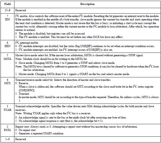
- I2C Control Register (I2CR)
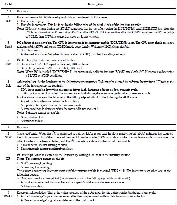
- I2C Status Register (I2SR)
5.5 I2C communication
- We look into int i2c_xfer(u32 base, struct imx_i2c_request *rq, int dir).
int i2c_xfer(u32 base, struct imx_i2c_request *rq, int dir)
{
unsigned int reg;
unsigned char i, data;
unsigned short i2cr;
int ret = 0;
if (rq->buffer_sz == 0 || rq->buffer == NULL)
{
printf("Invalid register address size=%x, buffer size=%x, buffer=%x\n",
rq->reg_addr_sz, rq->buffer_sz, (unsigned int)rq->buffer);
return -1;
}
/* Check if bus is free, if not return error */
if (is_bus_free(base) != 0)
{
return -1;
}
// reset and enable I2C
writew(0, base + I2C_I2CR);
writew(I2C_I2CR_IEN, base + I2C_I2CR);
/* Need wait at least 2 cycles of per_clk*/
hal_delay_us(5000);
// 1.2 clear both IAL and IIF bits
writew(0, base + I2C_I2SR);
// 1.3 assert START signal and also indicate TX mode
i2cr = I2C_I2CR_IEN;
writew(i2cr, base + I2C_I2CR);
i2cr = I2C_I2CR_IEN | I2C_I2CR_MTX;
writew(i2cr, base + I2C_I2CR);
i2cr = I2C_I2CR_IEN | I2C_I2CR_MSTA | I2C_I2CR_MTX;
writew(i2cr, base + I2C_I2CR);
// 1.4 make sure bus is busy after the START signal
if (wait_till_busy(base) != 0)
{
printf1("1\n");
return -1;
}
/* Set the Transmit bit */
i2cr |= I2C_I2CR_MTX;
writew(i2cr, base + I2C_I2CR);
// Step 2: send slave address + read/write at the LSB
data = (rq->dev_addr << 1) | I2C_WRITE;
if ((ret = tx_byte(&data, base)) != 0)
{
printf1("START TX ERR %d %d\n", __LINE__, ret);
if (ret == ERR_NO_ACK)
{
return ERR_NO_ACK_ON_START;
}
else
{
return ret;
}
}
// Step 3: send I2C device register address
if (rq->reg_addr_sz > 4)
{
printf("Warning register address size %d should less than 4\n",
rq->reg_addr_sz);
rq->reg_addr_sz = 4;
}
reg = rq->reg_addr;
for (i = 0; i < rq->reg_addr_sz; i++, reg>>=8)
{
data = reg & 0xFF;
printf1("sending I2C=0x%x device register: data=0x%x, byte %d\n",
base, data, i);
if (tx_byte(&data, base) != 0)
{
return -1;
}
}
// Step 4: read/write data
if (dir == I2C_READ)
{
// do repeat-start
i2cr = readw(base + I2C_I2CR);
writew(i2cr | I2C_I2CR_RSTA, base + I2C_I2CR);
// make sure bus is busy after the REPEATED START signal
if (wait_till_busy(base) != 0)
{
return ERR_TX;
}
// send slave address again, but indicate read operation
data = (rq->dev_addr << 1) | I2C_READ;
if (tx_byte(&data, base) != 0)
{
return -1;
}
// change to receive mode
i2cr = readw(base + I2C_I2CR);
if (rq->buffer_sz == 1)
{
// if only one byte to read, make sure don't send ack
i2cr |= I2C_I2CR_TXAK;
}
writew(i2cr & ~I2C_I2CR_MTX, base + I2C_I2CR);
// dummy read
readw(base + I2C_I2DR);
// now reading ...
if (rx_bytes(rq->buffer, base, rq->buffer_sz) != 0)
{
return -1;
}
}
else
{
// I2C_WRITE
for (i = 0; i < rq->buffer_sz; i++)
{
// send device register value
data = rq->buffer[i];
if ((ret = tx_byte(&data, base)) != 0)
{
break;
}
}
// generate STOP by clearing MSTA bit
imx_send_stop(base);
}
return ret;
}
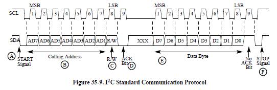
- I2C protocol
- Arbitration lost
- We might met this message in I2C communication, the message comes from read I2C status register.
{
printf("Error: arbitration lost!\n");
return -1;
}
- If several devices try to engage the bus at the same time, one becomes master. Hardware immediately switches devices that lose arbitration to slave receive mode. Data output to SDA stops, but SCL is still generated until the end of the byte during which arbitration is lost. An interrupt occurs at the falling edge of the ninth clock of this transfer if the arbitration is lost (I2SR[IAL] = 1), and the slave mode is selected (I2CR[MSTA] = 0). See the flow chart in Figure 35-13.
- If a device that is not a master tries to transmit or do a START, hardware inhibits the transmission, clears MSTA without signalling a STOP, generates an interrupt to the CPU, and sets I2SR[IAL] to indicate a failed attempt to engage the bus. When considering these cases, the slave service routine should first test I2SR[IAL], and the software should clear it if it is set. For Multi-master mode, when an I2C module is enabled when the bus is busy and asserts START, the I2SR[IAL] bit gets set only for SDA=0, SCL=0/1, SDA=1, and SCL=0, but not for SDA=1 and SCA=1, which is the same as bus idle state.
- Caution:
- We have met one Arbitration lost due to iMX53 TO1 power up sequence hardware setting not correct.,The I2C module works abnormal at this case. We captured I2C waveform and found after 9th CLK, SCL has a very narrow low waveform and then SDA raise high. It generate arbitration lost error. With fine tune hardware power up sequence, the I2C module works OK.
No comments:
Post a Comment