1. Introduction
USB revolutionized the PC peripheral space by making a very simple plug-and-play interface for users. As a result, many modern computers no longer support RS-232 serial COM ports, opting for the slimmer USB alternative. This can be an issue for the developer who needs a COM port for communication between a peripheral and host PC. A subset of the USB Communication DeviceClass (CDC) can be used to emulate a serial port providing a virtual COM port UART interface. This allows developers to use legacy applications with new products using the same COM port interface as before, with few hardware and software modifications.

Figure 1 USB CDC Virtual COM Port System
This application note describes the USB communications device class driver (or USB CDC) in detail and includes an implementation example for the Silicon Labs EFM32 Giant Gecko MCU.
1.1. Assumptions
This document assumes the following:
- A working knowledge of the C programming language.
- Familiarity with the USB 2.0 specification and terms and abbreviations defined by the USB specification.
- Familiarity with Silicon Labs EFM32GG development environment.
1.2. Features and Limitations
The CDC firmware implemented with this application note includes the following features:
- Emulates a serial COM port on PC that supports the CDC Abstract Control Model (ACM).
- Provides an abstract communication interface for data transfers between the host and the device.
- Handles standard Chapter 9 USB device requests.
- Handles CDC-specific requests from USB host.
- Notifies the USB host of status using an interrupt endpoint.
- Provides data communication with the USB host using a bulk endpoint.
- The following baud rates are supported: 600, 1200, 2400, 4800, 9600, 14400, 19200, 38400, 57600, 76800, 115200 and 230400 bps.
The example does not implement the following:
- No CTS/RTS control is performed, so flow control must be set to nonein the terminal program.
- RTS/DTR control is not implemented.
2. Relevant Documentation
EFM32 Giant Gecko Application Notes are listed on the following website: www.silabs.com/32bit-appnotes.
- AN758 IMPLEMENTING USB COMMUNICATION DEVICE CLASS (CDC) ON SiM3U1XX MCUs -- provides an implementation example on porting LUFA USB CDC on SiM3U1xx MCUs.
- AN0822 SIMPLICITY STUDIO USER’S GUIDE -- provides a description of the Simplicity Studio IDE features and environment.
- AN0065 EFM32 as USB Device -- provides a description of the EFM32 USB Device stack.
3. USB CDC Class
The USB communications device class (CDC) is a composite USB device class, and the class may include more than one interface. The CDC is used primarily for modems, but also for ISDN, fax machines, and telephony applications for performing regular voice calls. The Abstract Control Model subclass of CDC and bridges the gap between legacy modem devices and USB devices, enabling the use of application programs designed for older modems.
3.1. Class Requests
The class requests and class notifications supported are listed in Table 1.
Table 1. Abstract Control Model Requests
| Request | Code | Description |
|---|---|---|
| SET_LINE_CODING | 20h | Configures baud rate, stop-bits, parity, and numberof-character bits. |
| GET_LINE_CODING | 21h | Requests current DTE rate, stop-bits, parity, and number-of-character bits. |
| SET_CONTROL_LINE_STATE | 22h | RS232 signalused to tell the DCE device the DTE device is now present. |
These class-specific requests are used for device and call management.
3.1.1. Set Line Coding
This request allows the host to specify typical asynchronous line-character formatting properties.
| bmRequestType | bRequest | wValue | wIndex | wLength | Data |
|---|---|---|---|---|---|
| 00100001b | SET_LINE_CODING | 0 | interface | size of structure | line coding structure |
Table 2 defines the line coding properties.
Table 2. Line Coding Format
| Offset | Field | Size | Value | Description |
|---|---|---|---|---|
| 0 | dwDTERate | 4 | Number | Data terminal rate, in bits per second. |
| 4 | bCharFormat | 1 | Number | 0: 1 Stop bit 1: 1.5 Stop bits 2: 2 Stop bits |
| 5 | bParityType | 1 | Number | Parity: 0:None 1: Odd 2: Even 3: Mark 4: Space |
| 6 | bDataBits | 1 | Number | Data bits (5, 6, 7, 8 or 16). |
3.1.2. Get Line Coding
This request allows the host to find out the currently configured line coding. Table 2 defines the line coding properties.
| bmRequestType | bRequest | wValue | wIndex | wLength | Data |
|---|---|---|---|---|---|
| 10100001b | GET_LINE_CODING | 0 | interface | size of structure | line coding structure |
3.1.3. Set Control Line State
This request generates RS-232/V.24 style control signals. Table 3 defines control signal bitmap.
| bmRequestType | bRequest | wValue | wIndex | wLength | Data |
|---|---|---|---|---|---|
| 00100001b | SET_LINE_CONTROL_STATE | control signal bitmap | interface | 0 | none |
Table 3. Control Signal Bitmap
| Bit Position | Description |
|---|---|
| 15:2 | Reserved (Reset to zero). |
| 1 | Carrier control for half duplex modems. This signal corresponds to V.24 signal 105 and RS232 signal RTS. 0: Deactivate carrier. 1: Activate carrier. The device ignores the value of this bit when operating in full duplex mode. |
| 0 | Indicates to DCE if DTE is present or not.This signal corresponds to V.24 signal 108/2 and RS232 signal DTR. 0: DTE is not present. 1: DTE is present |
3.2. Class Notifictions
Table 4 shows the class notifications supported by the Abstract Control Model.
Table 4. Abstract Control Model Notifications
| Notification | Code | Description |
|---|---|---|
| SERIAL_STATE | 20h | Returns the current state of the carrier detects, DSR, break, and ring signal. |
Serial State
This notification sends an asynchronous message containing the current UART status.
| bmRequestType | bRequest | wValue | wIndex | wLength | Data |
|---|---|---|---|---|---|
| 10100001b | SERIAL_STATE | 0 | interface | 2 | UART state bitmap |
The data field for this notification is a bitmapped value that contains the current state of detects transmission carrier, break, ring signal, and device overrun error. These signals are typically found on a UART and are used for communication status reporting. A state is considered enabled if its respective bit is set to 1.
Note: The firmware example included with this application does not currently support state change
Table 5. UART State Bitmap
| Bit Position | Field | Description |
|---|---|---|
| 15:7 | Reserved (future use). | |
| 6 | bOverRun | Received data has been discarded due to overrun in the device. |
| 5 | bParity | A parity error occurred. |
| 4 | bFraming | A framing error occurred. |
| 3 | bRingSignal | State of ring signal detection of the device. |
| 2 | bBreak | State of break detection mechanism of the device. |
| 1 | bTxCarrier | State of transmission carrier. This signal corresponds to V.24 signal 106 and RS232 signal DSR. |
| 0 | bRxCarrier | State of receiver carrier detection mechanism of device. This signal corresponds to V.24 signal 109 and RS232 signal DCD |
3.3. Endpoint Configuration
Table 6 illustrates the endpoint configuration for the Abstract Control Model.
Table 6. UART State Bitmap
| Endpoint | Direction | Type | Max Packet Size | Description |
|---|---|---|---|---|
| EP0 | In/Out | Control | 64 | Standard requests, class requests. |
| EP1 | In | Interrupt | 16 | State notification from device to host. |
| EP2 | In | Bulk | 64 | Data transferfrom device to host. |
| EP3 | Out | Bulk | 64 | Data transfer from host to device. |
Figure 2 shows a standard CDC communication flow.

Figure 2. USB CDC Communication FLow
4. LUFA USB Stack
The USB CDC firmware example is based on the
LUFA open-source project. LUFA is an open-source complete USB stack released under the permissive MIT License. It includes support for many USB classes, both for USB Hosts and USB Devices. For USB Devices, the LUFA stack includes support for Audio Class, CDC Class, HID Class, Mass Storage Class, MIDI Class, and RNDIS Class. More information about the LUFA project can be found on the official website: http://www.fourwalledcubicle.com/LUFA.php- The USB CDC project contains a prebuilt LUFA USB stack documentation which locate at .\LUFA\Documentation\html. Double click on the index.html, the documentations shows in your default browser.

Figure 3. USB LUFA Libary Documentation
- This implementation support two boards of EFM32GG, STK3700 and DK3750. Default setting is DK3750, To change board selection, just modify macro definition in .\LUFA\Common\BoardTypes.h.
#if !defined(__DOXYGEN__)
    #define BOARD_                 BOARD_DK3750
    #if !defined(BOARD)
        #define BOARD              BOARD_DK3750
    #endif
#endif
For STK3700 board, there is no UART socket on board. UART signals are connected to EXP Header.

Figure 4. USART signals on STK3700 Expansion Header
5. USB CDC Driver
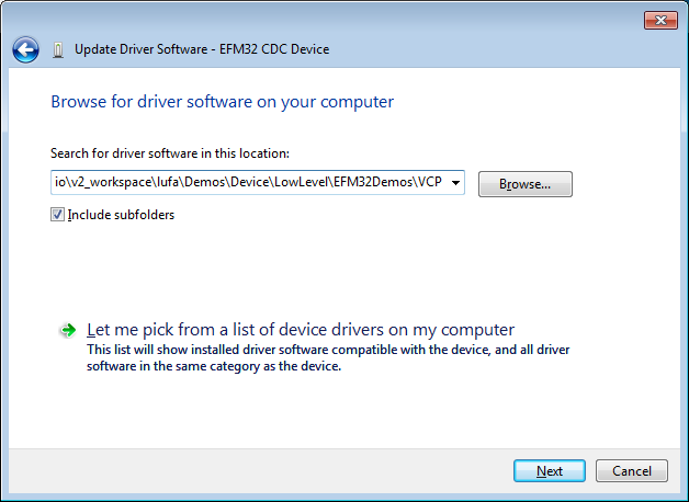
The CDC class is implemented in all releases of Windows, and the operatingsystem needs an INF file for the CDC driver. This INF file contains the Vendor ID and Product ID. If the VID/PID of the USB devices matches the INF file, Windows will load the driver described in the file. The VirtualSerial.inf file can be found in the.\Demos\Device\LowLevel\EFM32Demos\VCP directory.
Installing the Driver
To install the driver on Windows 7:
- Build the project and download firmware to the EFM32GG DK3750 board.
- Connect the USB cable between the Device MCU plugin board USB connector and the PC.
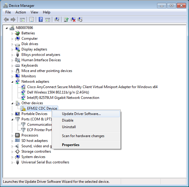
- Open Device Manager. The device will appear under Other devices as the EFM32GG CDC Device.
- Right-click on the EFM32GG CDC Device and select Update Driver Software.
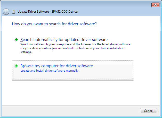
- Select Browse my computer for driver software.
- Select Browse my computer for driver software.
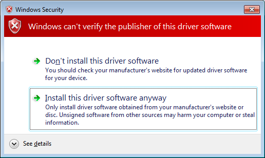
- Windows will display a warning. Select Install this driversoftware anyway.
- When the driver finishes installing,Windows will report the installation results.
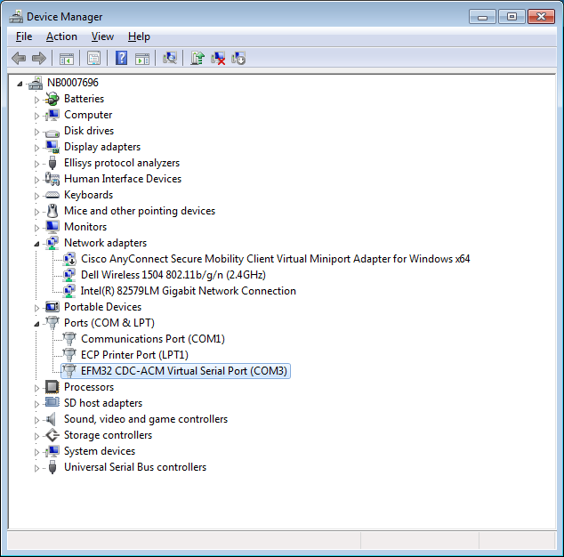
- Open Device Manager and observethe device. It will now appear under Ports (COM & LPT) with an assigned COM port number.

Source code
Source code can be found in https://github.com/MarkDing/lufa-efm32.
Github page in http://markding.github.io/lufa-efm32/.
CONTACT INFORMATION
Silicon Laboratories Inc. 400 West Cesar Chavez
Austin, TX 78701
Tel: 1+(512) 416-8500
Fax: 1+(512) 416-9669
Toll Free: 1+(877) 444-3032
Please visit the Silicon Labs Technical Support web page:
https://www.silabs.com/support/pages/contacttechnicalsupport.aspx
and register to submit a technical support request.
Austin, TX 78701
Tel: 1+(512) 416-8500
Fax: 1+(512) 416-9669
Toll Free: 1+(877) 444-3032
Please visit the Silicon Labs Technical Support web page:
https://www.silabs.com/support/pages/contacttechnicalsupport.aspx
and register to submit a technical support request.